Overview
Two 3 t induction furnaces melt the dry metal feeds into one checked iron-nickel alloy.
Area 13 melts the solid feeds into liquid iron-nickel. The feed is already metal, so no chemistry is needed. In each furnace, a water-cooled copper coil heats the metal with a strong magnetic field. Rock left in the feed forms slag, which is skimmed off.
A charging car weighs out each charge and feeds it into a furnace. A sample checks the nickel content. At 1,580 °C, the furnace pours one heat, a 3,000 kg batch, into a heat-proof ladle. A car takes it to casting.
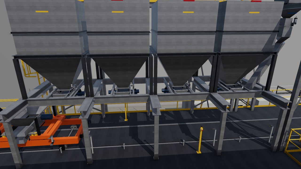
Process steps
- Four covered day bins hold the dry feeds: nuggets, concentrate, briquettes and returns.
- The charging car weighs out 3.15 t per heat, in two trips.
- The furnace melts the charge at full power for 38 minutes.
- A sample checks for 15 to 40 % nickel. A rake removes the slag.
- At 1,580 °C, the furnace tilts and pours 3,000 kg into the ladle.
- The ladle car leaves for casting, and the second furnace pours 29 minutes later.
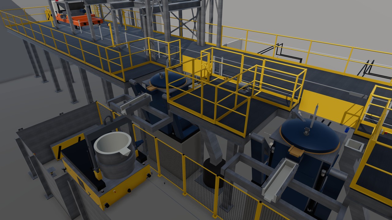
The line in the twin
Turning view
Specifications
The equipment list
| Unit | Function | Key data |
|---|---|---|
| Induction furnaces, 3 t | Melt the charge, then tilt to skim and pour. | 3 t per heat, 58 min cycle |
| Furnace power supplies | Feed the furnace coil with medium-frequency power. | 3,000 kW each, about 2,000 kWh per heat |
| Charging car with weigh hopper | Weighs out each charge and feeds it into the furnace. | 3.15 t in two trips, stops within ± 5 mm |
| Ladle transfer car | Carries the ladle to casting and weighs the pour. | 3,000 ± 30 kg per pour, 48 V battery |
| Spark spectrometer | Measures the nickel content of one sample per heat. | Result after 4 min, accepts 15 to 40 % Ni |
| Safety laser scanners and locked pit gate | Block furnace motion and pouring while a person is near. | Deck and pit scanners, guard-locked gate |
Links lead to the makers' public product pages and are given for reference only. This site is independent work, not affiliated with, sponsored or endorsed by any manufacturer. The makers are responsible for the content of their pages. Trademarks belong to their owners.
Control and safety
- The furnace sequence is defined from charge to pour, and seven fault test cases are specified.
- A pour starts only when the ladle car is locked in place and the pit is clear.
- The charge must be dry, because water on liquid metal causes a steam explosion.
- The single devices are modelled from the datasheet and tested against the PLC (control computer).
The hand-overs
| From | 6.51 t/h of dry feed: nuggets, concentrate, briquettes, casting returns and a flux additive. |
| To | Ladles of 3,000 ± 30 kg at 1,580 °C to casting, with a heat record each. |
The devices and signals
- Line PLC: 38 input and output terminals in 3 I/O stations.
- 141 line signals: 40 digital inputs, 28 digital outputs, 14 analog, 35 safe inputs, 15 safe outputs and 9 others.
- Two vehicle PLCs: the charging car (13 terminals, 38 signals) and the ladle car (19 terminals, 36 signals).
- 4 variable speed drives for the bin drawers. The two 3,000 kW furnace power units get a safe enable.
- Safety devices: 7 emergency stop stations, 2 safety laser scanners, 1 pit gate with guard locking, 5 coded safety sensors and 2 safety position switches. Each car has 2 more scanners.
- Process sensors: 2 pyrometers, 5 temperature sensors, 4 radar level sensors, 2 encoders and a radio tag read head.
The safety functions
- Emergency stop: the furnace power and the hydraulics stop at once (stop category 0). Valves hold each furnace at its angle.
- A tap starts only with the pit field free, the pit gate locked and the ladle car pinned. The gate unlocks only when no tap runs and the car is at rest.
- The scanners are rated performance level d, category 3, by their data sheet.
- Cars: all safety on board. A person in a scanner field gives a controlled stop, then safe torque off (stop category 1).
- Radio carries jobs and status only, never a safety function.
- Target: performance level d, a target and not a claim.
The tests run in the twin
- In test against the PLC since 2026-10-21: first unit test runs, then test windows 4 to 11, the last on 2026-11-01.
- Window 8 (2026-10-31): line 710 checks, 707 passed, 3 failed by test timing, no PLC fault. Safety 58 of 58, charging car 152 of 152, ladle car 91 of 91.
- Seven fault tests are defined, from an emergency stop during a furnace tilt to a person in front of the charging car.
- Open: in the visible 3D run the cars still read their scanner fields as not free.
About this page
In the scenario, this area turns the sorted metal of 16 Psyche into liquid alloy, one 3 t heat every 29 minutes.
Real devices, built from real data
Every machine and device in this twin is a real industrial product from the makers' catalogues. They range from sensors, valves and drives to safety scanners, load cells and RFID readers. Each model is built from the product's published data: dimensions, sensing ranges, signals, rated values, parameters and timing.
The PLC programs use the devices' real interfaces and parameters. Before any hardware existed, the twin found hundreds of faults in the plant design and the programs. So a real commissioning would need fine tuning, not a redesign.